BASE LAMINATE MATERIALS
Printed circuit boards (PCBs) incorporate numerous technologies and constructions, adapted to the electrical, thermal, and mechanical constraints of each application. Epoxy (FR-4), PTFE (Teflon), aluminum, polyimide… each base material meets a specific need and requires adapted manufacturing processes. The choice of substrate is a key parameter for the performance and reliability of the electronic board. PMB offers a wide range of laminates, from FR-4 (glass epoxy) to flexible polyimide, selected according to the performance, reliability, and requirements of each project. Supplier selection is strategic. PMB has qualified leading manufacturers in their market:



Supported materials:
FR4 , IMS (aluminium) , CEM3 , POLYIMIDE , ROGERS
RIGID Laminates
PMB offers an optimized range of “RIGID” laminates – FR-4, rigid polyimide and CEM-3 – carefully selected from the two Chinese manufacturers leading in terms of volume: "KB Laminates" and "Shengyi" Explore each material below, its key technical characteristics and download the datasheet (PDF)
# RIGID LAMINATES - STANDARD FR4 for 1 and 2 layers PCB
For single- and double-sided circuits, PMB uses products from the manufacturer « KB Laminates », the global leader in standard laminates. This choice guarantees:
- Standard laminate with excellent price/performance ratio
- worldwide availability and certifications
- Long-termcontinuïteit reliability of the manufacturer and product references
| Property | Unit | IPC TM 650 | KB 6164 | KB 6165 |
|---|---|---|---|---|
| TG | °C | 2.4.25 | 140 | 153 |
| Cte-z | ppm/°C | 2.4.25 | 45 | 42 |
| Dielectric constant | etched@1MHZ | 2.5.5.2 | 4.6-4.8 | 4.6-4.8 |
| Electrical strengh | KV/mm | 2.5.6.2 | ≥ 28 | ≥ 28 |
| Dieletric breakdown | KV | 2.5.6 | ≥45 | ≥45 |
| Surface resistivity | MO | 2.5.17.1 | 2.2×10^8 | 2.4×10^8 |
| Tracking resistance CTI | V | 2.4.24 | ≥175 | ≥175 |
| Td260 | min | 2.4.24.1 | >60 | >60 |
| Td288 | min | 2.4.24.1 | >15 | >20 |
| Td value | °C | 2.4.24.6 | 330 | 348 |
| Flammability | Rating | UL94 | V-0 | V-0 |
# "RIGID" LAMINATES - PREMIUM FR4 for multilayers PCB
For multilayers PCB more technical, PMB uses "premium" products from the manufacturer SHENGYI Laminates, considered the global leader in high-tech laminates. This choice guarantees:
- Superior quality laminates. Precise / consistent flatness. Uniform copper thickness
- Better resistance to thermal cycling
- Lower Z-axis CTE - improves PTH reliability
Other laminates and thicknesses
| Property | Unit | IPC TM 650 | S1000H | S1000-2M | S1600 |
|---|---|---|---|---|---|
| TG | °C | 2.4.25 | 155 | 185 | 135 |
| Cte-z | ppm/°C | 2.4.25 | 37 | 41 | 55 |
| Dielectric constant | etched@1MHZ | 2.5.5.2 | 4.6 | 4.7 | 4.7 |
| Electrical strengh | KV/mm | 2.5.6.2 | - | - | - |
| Dieletric breakdown | KV | 2.5.6 | >45 | >45 | 60 |
| Surface resistivity | MO | 2.5.17.1 | 3.5*10^7 | 2.2*10^7 | 5*10^7 |
| Tracking resistance CTI | V | 2.4.24 | PLC3 | PLC3 | PLC0 |
| Td260 | min | 2.4.24.1 | >60 | >60 | 15 |
| Td288 | min | 2.4.24.1 | 20 | 30 | 2 |
| Td value | °C | 2.4.24.6 | 348 | 355 | 310 |
| Flammability | Grade | UL94 | UL94-V0 | UL94-V0 | UL94-V0 |
# "RIGID" LAMINATES - VERY HIGH TG POLYIMIDE (TG 250)
Polyimide laminates are used for PCBs designed to operate at elevated temperatures. They provide high thermal stability and maintain mechanical and dielectric performance in demanding environments. Polyimide materials are widely used in following applications: satellites / avionics / radar systems / flight control electronics /space electronics
| Property | Unit | IPC TM 650 | SH260 | VT901 |
|---|---|---|---|---|
| TG | °C | 2.4.25 | 250 | 250 |
| Cte-z | ppm/°C | 2.4.25 | 45 | 50 |
| Dielectric constant | etched@1MHZ | 2.5.5.2 | 4.12 | 4.5 |
| Electrical strengh | KV/mm | 2.5.6.2 | 85 | 54 |
| Dieletric breakdown | KV | 2.5.6 | 40 | 60 |
| Surface resistivity | MO | 2.5.17.1 | 4.8*10^8 | 5*10^8 |
| Tracking resistance CTI | V | 2.4.24 | - | PLC4 |
| Td260 | min | 2.4.24.1 | - | >60 |
| Td288 | min | 2.4.24.1 | - | >60 |
| Td value | °C | 2.4.24.6 | 429 | 390 |
| Flammability | Grade | UL94 | UL94-V0 | UL94-V0 |
# "RIGID" LAMINATES - CEM3 (THERMAL)
Thermal CEM-3 is an epoxy/glass composite laminate, similar to FR4. The main differences versus FR4 are:
- Non-woven glass reinforcement.
- Improved heat dissipation (higher thermal conductivity).
- Distinctive milky-white appearance.
Due to its non-woven glass-mat core, CEM-3 is most commonly used for single-sided and double-sided boards and is generally recommended for low layer counts. It is widely used for LED lighting/driver boards and power supply boards.
We offer the following options:
- Material thickness: 0.9 to 1.8 mm range
- Finish copper thickness: 35 µm and 70 µm.
Data sheet :SHENGYI ST215 (CEM3)
# “RIGID” LAMINATES - HALOGEN-FREE FR-4
Halogen-free FR-4 uses a halogen-free flame-retardant material system and is suitable for PCBs requiring environmental compliance, thermal reliability, and multiple reflow cycles. Material selection can be evaluated against IEC 61249-2-21 for chlorine, bromine, and total halogen content; actual compliance is subject to the test report for the selected material.
- Supports standard-Tg and high-Tg halogen-free FR-4 materials
- Suitable for lead-free reflow soldering and repeated thermal cycling
- Material references, UL certifications, and halogen-free test data are available
- Supports automotive electronics, industrial control, power supplies, and export products
Common halogen-free PCB laminate materials are S1155 (FR-4) and S1165 (FR-4). The table below lists selected parameters for these laminates:
| Material | Tg (°C) | Td (°C) | CTE (ppm/°C) | Td260 (min) | Td288 (min) |
|---|---|---|---|---|---|
| S1155(FR-4) | 140 | 380 | 41 | 60 | 60 |
| S1165(FR-4) | 170 | 360 | 40 | 60 | 15 |
We offer advanced halogen-free PCB manufacturing services. Refer to the table below for our full capabilities:
| Item | Manufacturing Capability |
|---|---|
| Quality Grade | IPC Class 2 |
| Layer Count | 2-layer to multilayer |
| Order Quantity | 1–10,000+ pieces |
| Lead Time | 2 days–5 weeks |
| Material | S1150G, S1165 |
| Board Size | Min. 6 × 6 mm; Max. 457 × 610 mm |
| Board Thickness | 0.4–6.5 mm |
| Finished Copper Thickness | 0.5–2 oz |
| Minimum Trace Width / Spacing | 3/3 mil |
| Solder Mask | As specified in the files |
| Solder Mask Color | Green, white, blue, black, red, yellow |
| Silkscreen | As specified in the files |
| Silkscreen Color | White, black, yellow |
| Surface Finish | HASL (Hot Air Solder Leveling) Lead-Free HASL (RoHS) ENIG (Electroless Nickel Immersion Gold, RoHS) Immersion Silver (RoHS) Immersion Tin (RoHS) OSP (Organic Solderability Preservative, RoHS) |
| Minimum Annular Ring | 4 mil |
| Minimum Drill Diameter | 6 mil |
| Other Processes | Gold fingers Blind/buried vias |
The following industries commonly require or recommend halogen-free PCBs:
- Consumer electronics: smartphones, laptops, and wearable devices
- Automotive electronics: engine control units, infotainment systems, and sensors
- Aerospace and defense: avionics and guidance systems
- Medical: implantable medical devices and imaging equipment
- Green energy: solar equipment, energy storage systems, and wind power equipment
Especially suitable for applications with flame-retardancy requirements or heightened sensitivity to corrosion and long-term reliability.
Material references and process parameters will be engineering-reviewed according to the stack-up, board thickness, copper thickness, operating temperature, and reflow conditions. Please provide Gerber files, the stack-up, and the target halogen-free standard when requesting a quotation.
HF PCB (HIGH FREQUENCY)
Rogers type laminates are hydrocarbon-ceramic materials designed for high-frequency PCB applications (broadband circuits, sensors, etc.). They feature a tightly controlled dielectric constant (Dk) and low losses, enabling accurate impedance control. For prototypes and small series production, PMB offers the following laminate references:
IMS - ALUMINIUM CORE
IMS (Insulated Metal Substrates) are laminates with an aluminium core, primarily used for their excellent heat dissipation and thermal management. IMS PCBs are mainly used in LED lighting and power supply applications, where efficient thermal management is critical. PMB offers single-sided and double-sided IMS solutions. For double-sided IMS, please contact us to confirm feasibility. As an option, one side of the PCB can be covered with an adhesive.3M-9460 Black (matte or glossy) and white are the most common solder mask colors. The choice is driven by optical performance: white improves light reflection, while black limits reflections and absorbs stray light. SMI substrates are available with different insulation thicknesses between the copper and the aluminium base. PMB supplies 120 µm as the standard insulation thickness.
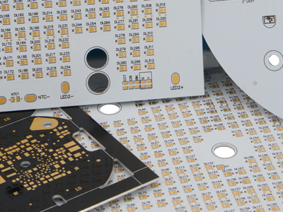
PMB offers the following IMS material references:
Ceramic PCB
Ceramic PCBs use advanced ceramic substrates such as aluminum oxide and aluminum nitride to dissipate heat efficiently while maintaining electrical insulation. They are suitable for designs where standard FR-4 cannot meet thermal management, electrical performance, or long-term reliability requirements. Ceramic substrates provide a direct heat-dissipation path from component hot spots, creating a stable platform for high-power, high-temperature, and high-frequency electronic products.
Why Choose a Ceramic Substrate?
- High thermal conductivity efficiently transfers heat generated by power devices and LEDs.
- Combines electrical insulation with stable dielectric performance for demanding circuit designs.
- Low coefficient of thermal expansion; aluminum nitride more closely matches the thermal expansion of silicon.
- Resistant to high temperatures, moisture, and chemical corrosion, making it suitable for harsh operating environments.
Common Ceramic Substrate Materials:
| Material | Thermal Conductivity | Key Features | Typical Applications |
|---|---|---|---|
| Al₂O₃ (Aluminum Oxide) | 24–30 W/m·K | Relatively cost-effective, with high mechanical strength and chemical corrosion resistance. | Industrial electronics, automotive sensors, and LED lighting. |
| AlN (Aluminum Nitride) | 170–230 W/m·K | Excellent thermal conductivity, low coefficient of thermal expansion, and good electrical insulation. | Power modules, high-power LEDs, and 5G infrastructure. |
| SiC (Silicon Carbide) | 120–200 W/m·K | Good high-temperature stability, high hardness, and chemical inertness. | Aerospace, industrial control systems, and high-temperature electronic equipment. |
| BeO (Beryllium Oxide) | 220–350 W/m·K | Extremely high thermal conductivity, but requires specialized safety handling procedures. | Engineering-reviewed microwave and high-frequency systems. |
Thermal conductivity values are reference ranges for the materials. Final selection depends on the specified ceramic grade, metallization system, assembly process profile, and actual application environment.
Available Structures and Manufacturing Methods:
- Choose single-layer or multilayer ceramic structures according to circuit density and thermal requirements.
- Thick-film processing is suited to robust, reliable screen-printed conductors for industrial environments.
- Thin-film processing is suited to precision metallization, fine-pitch features, and high-frequency routing.
- A hybrid ceramic and FR-4 construction can be used when performance must be balanced with system cost.
Typical Applications:
- Compact assemblies for power electronics, LEDs, or constrained thermal paths.
- Products operating in high-temperature or repeated thermal-cycling environments that require high substrate stability.
- RF and high-frequency designs requiring stable dielectric performance and low loss.
- Applications exposed to moisture, corrosive media, or harsh mechanical conditions.
When requesting a quotation, please provide the operating temperature, power dissipation, insulation requirements, frequency range, and proposed stack-up. Material grade, layer count, copper thickness, via structure, and surface finish must be confirmed through engineering review before production.
FLEX PCB
Flexible PCBs (FLEX) provide a flexible interconnect between boards and allow electronics to fit into confined or moving areas where rigid PCBs are impractical. FLEX circuits are thin and lightweight, and their geometry can be tailored to the mechanical constraints of the final product. They also provide good vibration resistance, which is why they are widely used in compact, high-integration electronic devices. In those products,POLYIMID is used as the base material.

Polyimide thicknesses:
- 12 µm
- 25 µm (standard)
- 50µm
Finished copper thicknesses:
- Flex 1 layers : 18, 35, 70 μm
- Multilayer FLEX : 25, 45, 85 µm
Stiffeners — One or more stiffeners can be added to a FLEX to reinforce specific areas (e.g., connector zones, SMD assembly areas, or to restrict bend regions). Stiffeners can be applied on the top side, bottom side, or both. They are bonded using a heat-activated adhesive.
Stiffener - Thicknesses available:
- Polyimid : 0.075 .. 0.25 mm
- FR4 : 0.3 .. 1.5 mm
As an option, an adhesive layer can be added. The default reference is 3M 9077.
RIGID-FLEX
A RIGID-FLEX PCB is a hybrid construction that combines rigid PCB sections and flexible interconnects within a single structure.
This architecture reduces connectors and cabling, improves reliability, and saves space within the final product.
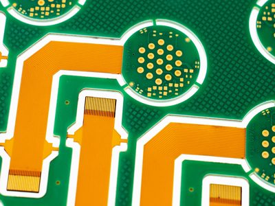
Manufacturing rigid-flex PCBs combines rigid and flex processes and requires proven expertise in several key steps:
- The milling process
- Metallization of layers and vias
- Layer lamination (pressing)
Few manufacturers of printed circuits master this technology. However, Rigid-Flex offers many advantages in terms of size, reliability and weight reduction.
It is used in many application fields such as medical devices, aeronautics and automotive electronics.
- Reliability: elimination of inter-card connectivity, which represents the most significant source of defaults in electronics.
- Space saving: elimination of inter-card connectors, with fewer solder points.
- Gain on weight.
- Cost reduction: elimination of connectors and inter-card cables.
- Improved signal transmission through homogenization of the conductors.
- Save time: assembly already done
PMB.com offers the following standard stack-ups
- Rigid material: FR4 TG 180 (S1000-2).
- Flex material: polyimide.
- Rigid thickness: 0.25 .. 3.2 mm.
- Rigid layers: up to 8.
- Flex layers: 2.
- Rigid surface finish: ENIG.
- Flex surface finish: ENIG.
- Maximum panel size: 1020 x 520 mm.
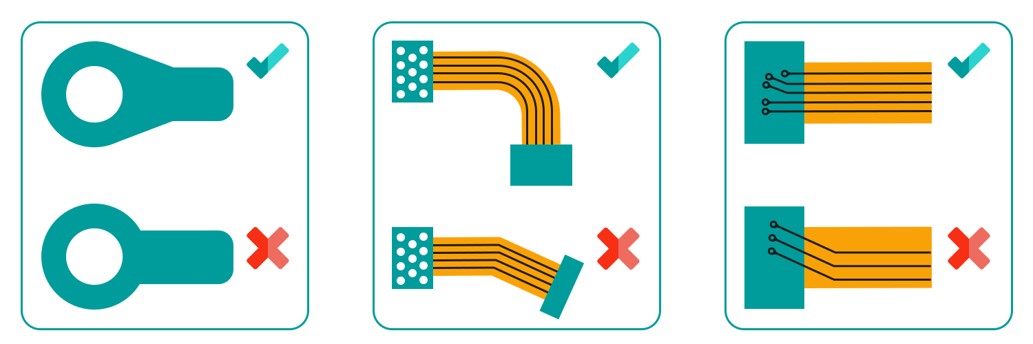
For reliable Rigid-Flex designs, PMB recommends the following layout rules:
- No via in flexible zone.
- Design the via with "teardrops".
- Prefer rounded corners with large radius on the flexible part.
- No change in width or direction of the tracks in the folding area.
- Tracks perpendicular to the rigid flex connection area.